Closed for summer holidays until August 12.
Orders are sent once approximately every two weeks.
For support, use email.
LED-kort, Power driver

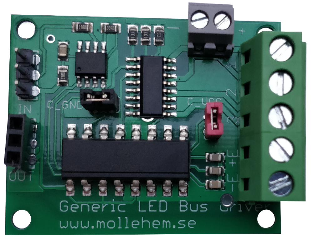 led-power_v2.png
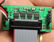
This driver card is connected to the standard serial bus for LEDs used on Illumination, Panel and Signal decoders etc.
The driver card allows heavier power consumers, than small LEDs, to be connected. Examples of such are relays and LED spotlights.
The card has three outputs, ie can control three different power consumers, each output max 0.8A.
For small currents and a voltage of 5 volts, the serial bus's own current can be used. For larger currents and / or higher voltages, another power source is connected to the card.
The card is connected to the regular LED series bus on e.g. a panel decoder and is defined as ordinary LEDs to the panel decoder.
Connections
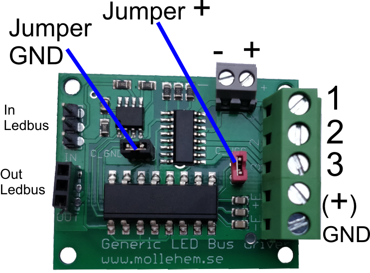
The LED bus is connected to connection "In". This cable comes from the previous LED card or from the controlling decoder.
Subsequent LED cards are connected from "Out" on the this card.
On the "+/-" upper terminal, 5 volts can be sourced from the serial bus.
Alternatively, an external power supply can be connected here if such is to be used. Note, that if an external power supply is used, the "+" and "gnd" jumpers must be removed. An external power source connected here must not find it's way to the LED bus, which happens if the jumpers is left in place!
The large terminal on the right is the output connections for what is to be operated.
"1", "2" and "3" are connections for "led", 1,2, and 3, respectively. These outputs are of the type "open collector", ie they connect the output to minus (GND) when they are active and they are disconnected otherwise.
GND on the large terminal is minus to which "1", "2" and "3" connected when these are active.
"(+)" can be used when inductive loads are connected, e.g. relay coils. Inductive loads can create an "interfering current" when a coil is switched off and this is avoided by connecting the +side of the coil here.
If you have loads that could be distrurbing for decoders and other things, the output part of the card should be separated from the rest of the system. In this case, remove the two jumpers and add external power to the "+/-"-terminal. This can be the same power source (DC) as is used to supply the load connected to the card.
Below are a number of examples of connection.
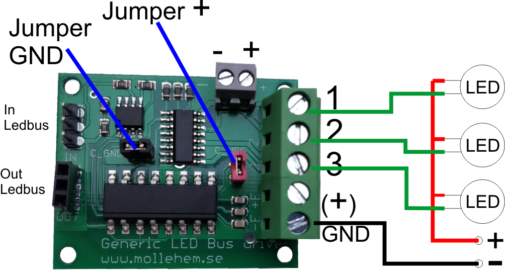
Control of spotligths
Spotlights of type 12v or 24v LED, that is used for kitchen and bathroom lighting, can be used with the card.
These are connected as shown:
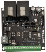
Control of MGP relay card
MGP relay card can be used with this LED board. In this way, powerful power consumers can be controlled and / or AC loads.
Relay card is connected as shown:
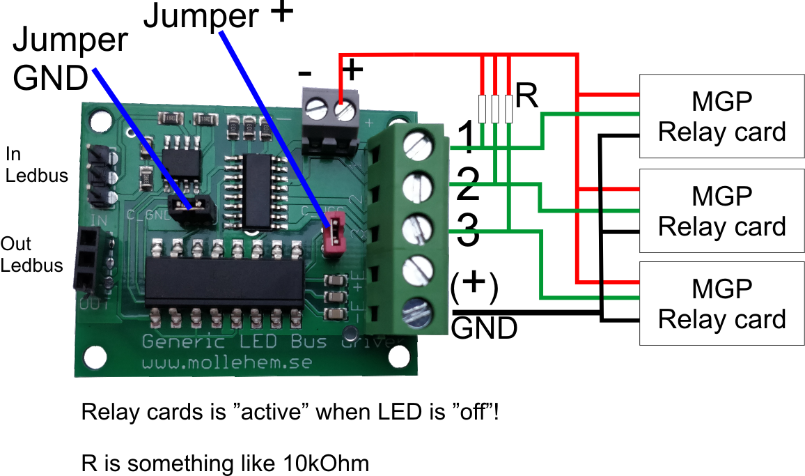
The relay cards from MGP can be powered from the LED bus. This is done by connecting "+" to the relay cards.
Note the three resistors connected from "+" to the respective output. A suitable value for these is 10kOhm.
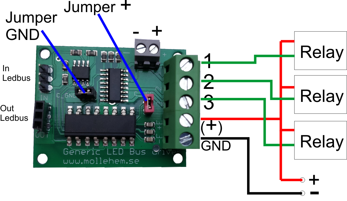
Control of ordinary relays
To control larger loads and loads where you want to use alternating current (AC), ordinary relays can be used.
Note that with relays you should connect "(+)" to the plus side of the relay, in order to remove the reverse currents that the relays can generate.
You can also consider removing the jumpers to insulate the card from the system's LocoNet / decoders, etc. In that case, you also connect the drive voltage of the relays to the "+/-" terminal.